-
jess
macleod
Shireen Elhabian
tag
shapeworks-dev-support
Text archives Help
- From: Allen Sanderson <allen@sci.utah.edu>
- To: HONG XU <u0867999@utah.edu>
- Cc: Alan Morris <amorris@sci.utah.edu>, Karthik Karanth <karanth.karthik@gmail.com>, "shapeworks-dev-support@sci.utah.edu" <shapeworks-dev-support@sci.utah.edu>
- Subject: Re: [shapeworks-dev-support] point splitting direction
- Date: Mon, 2 Nov 2020 17:08:23 -0700
- Ironport-sdr: BgGAOL861pl2znRaXx6YeBB17vPjY0YPk8BnNpi4P8L1w5erHA06Y6FHA4bLtcE560g5EzlVQM GsHteF0G5+gwThPH/ujIEUfr4lCcfhxFFpzvgo9PVosp0sUwNPeCBMpLis/rP53tFVBnbSNtn1 0FlRbyf+5i4bXXZ8vzU9bGnEkwR9kHuySPfIcwSlECxFzPH4+/y/MYcQANGuHaGVKxdXmn7OsT 8aFW0chW28FA67agJkhvydlqTMnJHBBrTnv3JB91OVULeSV+AGPDMJcBp6EyI0s9GLeOfpt5mA ks4=
Hi,
I thought I would give everyone a brief update as Hong and I meet today to discuss this issue. First props to Alan for the new checkpoint paradigm, as we would not have been able to figure out the issue without it.
Nutshell summary. What Hong and I discovered is that when seeding the corresponding particles are not splitting in the same direction or magnitude as expected. When this occurs along an edge on an open surface it has unintended consequences. It has similar unintended consequences on the interior as well.
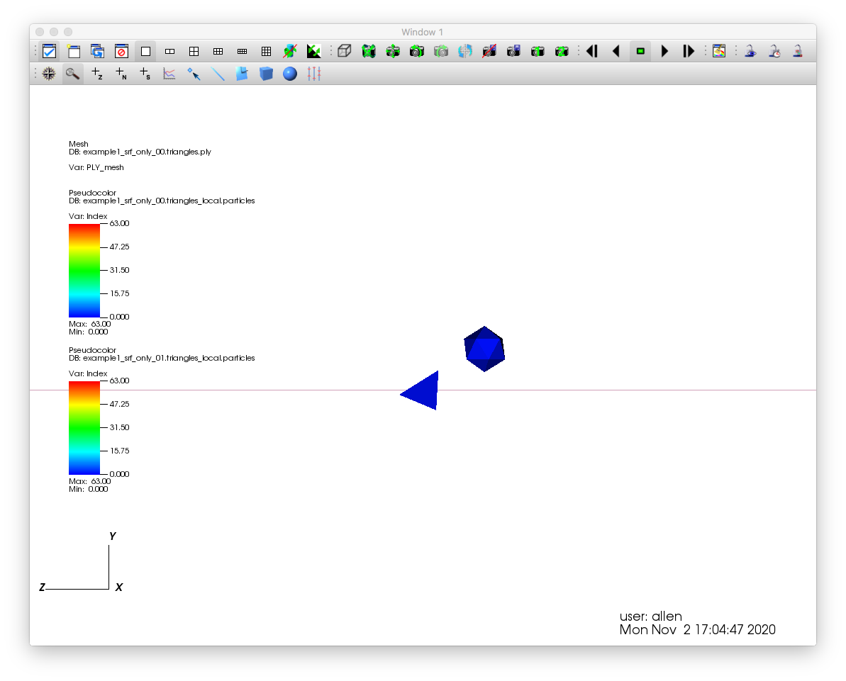
First image, (very zoomed in) there are two points both blue that are the original points (a tetrahedron (dataset 1) and a icosahedron (dataset 2)) from the previous correspondence phase, they are nearly coincident as one would expect as the mesh intros area is basically the same for both data sets.
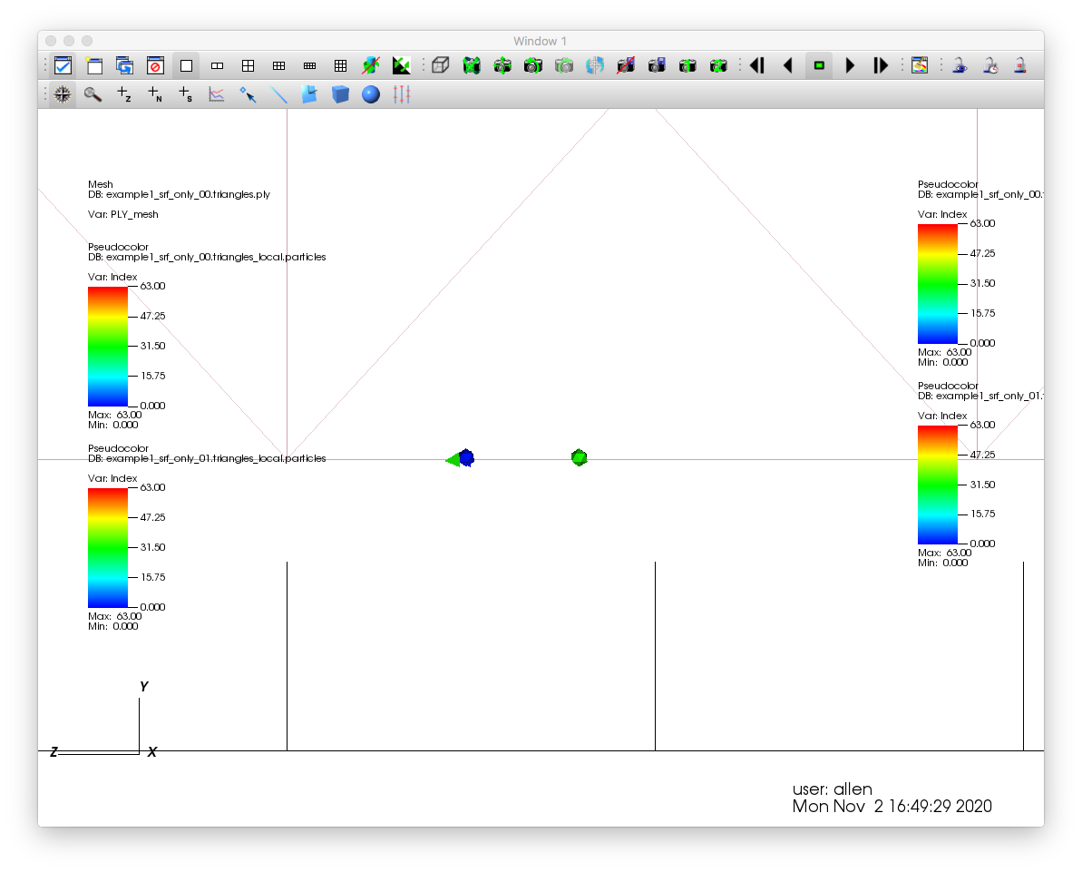
Second image, the split point from data set 1 is the green tetrahedron, the split point from data set 2 is the green icosahedron. One goes to the left, the other to the right. One would have expected both to be in the same direction and offset, they are not.
To show what happens down stream, I made two movies, the first shows the seeding phase (250 iterations), and the first part of the correspondence phase (the first 750 iterations).
Hong has all of the data plus my ancillary scripts and session files to look at what is happening within VisIt.
Cheers,
Allen
Attachment:
SeedingPhase.mpg
Description: MPEG movie
Attachment:
CorrespondencePhase.mpg
Description: MPEG movie
On Oct 30, 2020, at 3:32 PM, HONG XU <u0867999@utah.edu> wrote:Thanks for bringing this to my attention. The current particle splitting procedure happens in itkParticleSystem.txx::AdvancedAllParticleSplitting. The current implementation moves each set of corresponding particles in a random direction and checks that it doesn't violate any cutting-plane constraints after snapping to the surface. The reason we have gone for random at the moment is that this will guarantee that if there is a feasible point (considering cutting-plane constraints) at a certain d distance away, the particle splitting will find it. I will look at the paper you sent.The mechanism is quite simple, so I have not seen any problems testing in the image domain. Shireen and I did talk about potential issues with badly behaved surfaces where snapping to different surfaces might project the same vector onto different sides of the split particle. Our datasets have not seen this behavior to my knowledge, so it'd be great to study something that does if this were the problem. This problem should have presented before as well, so the new method should not be worse than the current one.I can't see anything suspicious in the particle splitting code itself. If you can give me instructions and data to replicate your results, I will look into it. Also, how do you get those visualizations? I am at a loss when visualizing stuff and mostly rely on print statements.Thanks Alan and Allen,HongFrom: Alan Morris <amorris@sci.utah.edu>
Sent: Friday, October 30, 2020 2:59 PM
To: Allen Sanderson <allen@sci.utah.edu>
Cc: HONG XU <u0867999@utah.edu>; Karthik Karanth <karanth.karthik@gmail.com>; shapeworks-dev-support@sci.utah.edu <shapeworks-dev-support@sci.utah.edu>
Subject: Re: [shapeworks-dev-support] point splitting directionCorresponding particles are supposed to be splitting in the same direction. If they are not then this is likely a regression in the newer particle splitting code. Hong?AlanOn Fri, Oct 30, 2020 at 2:18 PM Allen Sanderson <allen@sci.utah.edu> wrote:Hi Alan,Based on what I am seeing it is not quite that. I see two issues:
- Spitting distance needs to be dynamic with each iteration and based off the local distance between points on the surface.
- Splitting direction should be consistent across a set of correspondence points.
For #1 It appears that the distances do vary. But perhaps not like they should.For #2 I am expecting each set correspondence points to be in the offset in same direction. I do not see that. Which I think is the greater issue over the distance.For example, when splitting the original correspondence points (both a box which are co-incident), one is to the “left” and one is to the “right” (first image). But then for the second point one is to the “right” and the other is to the “left” (second image). Completely opposite. For both the distance also varies.Now when viewed together one can see the problem. The second set surrounds the first set and points cannot get around each other during either the initialization or optimization phases without really cranking up the relative_weighting which causes other issues.I have been playing around with both the scaling and the relative_weighting. Scaling without increasing the weighting results in worse correspondence. Increasing the weighting improves the results though comes at a cost of losing differences.What my intuition says is that when splitting is that the points for the new correspondence set each use the same distance and direction modulo the variation in the parent point location and surface. However what I see is completely the opposite random directions and distances. The last image shows a good example for the interior.Now the above is based on the fact that after 16 points I am doing the optimization phase. However, if I do the optimization only at the end the results are bad, whereas with the same parameters but doing the optimization after 16 points the results are really bad. Which perhaps not surprising because there is more randomness with the former. In both cases much worse with scaling.So for the first issue and the distance, as Karthik is working on the intra-point geodesic distances the information for dynamically setting the seed distance for meshes would be available.For the second issue the same orientation should be used.So basically instead of random distance and orientation for each new seed. Get a random distance and orientation and use for all new correspondence points for the first set, the repeat for the second set. I would like to try that. In looking at the Optimize.cpp file there are not any substantive comment to know exactly where anything is happening. So some guidance is needed.Regarding the particle splitting, not sure what direction Hong is going but early on I was reviewing some of the Poison disk sampling schemes. Our colleague next door Cem Yuksel has a paper on it:I think some of these ideas could be used rather than just a random seeing and using the optimization.Cheers,AllenAllen SandersonSCI InstituteUniversity of Utah
<Screen Shot 2020-10-30 at 1.25.42 PM.png><Screen Shot 2020-10-30 at 1.30.25 PM.png><Screen Shot 2020-10-30 at 1.30.13 PM.png><Screen Shot 2020-10-30 at 2.05.19 PM.png>On Oct 29, 2020, at 8:30 PM, Alan Morris <amorris@sci.utah.edu> wrote:Allen,If I had to guess, I would say that you are right that the splitting is the problem. We've discussed this several times as a group that the splitting distance needs to dynamically account for the current spacing between particles. I think what can happen is that the splitting distance is pushing particles beyond neighbors and this location is shape dependent, then afterward they are unable to move past neighbors to correct the correspondence. I believe for image based optimizations, the spacing is used for the splitting distance. For meshes, I think Oleks just used 1.0. So the scale of the mesh is probably going to affect this. You could try/test this by scaling the units of your mesh up by 100 or something.Hong has recently been working on particle splitting. I thought he was going to tackle this issue as well, but I don't think he has yet.AlanOn Thu, Oct 29, 2020 at 2:53 PM Allen Sanderson <allen@sci.utah.edu> wrote:Hi,I need a bit of a pointer to code as I have I run into an issue where points have split in such a way that they cannot get around each other. I am working with two surface meshes and after a split the optimization is done as well.Some relevant parameters:"iterations_per_split" : 250,"optimization_iterations" : 2500,"initial_relative_weighting" : 0.75,"relative_weighting" : 5,The first image shows the point location for 32 points after the optimization. Points are co-incident as I would expect except for at the 6 o’clock position which is where there is a surface difference.The second image is right after a split from 32 to 64 points. The vector shows the distance between points. Now my expectation is that after the split that the distance would be small. That is each set of correspondence points would use the same offset with perhaps some minor variance due to a difference in the surfaces. As such, the distance between correspondence points would remain relatively small because of optimization step having been previously performed. However that is not the case as there are quite a few relatively large vectors.In the third image I have highlighted two areas that each have two sets of correspondence points within. It is easy to see that there are two sets in each as it looks like a double headed vector. The point ordering is as follows 1A 2B 2A 1B. With 1A and 2A being one correspondence set and 1B and 2B being the other.The forth image shows the results after the both the initialization and optimization. Where the points could not “get around” each other because of what I would call a push pull situation. Now one could say that this case is an edge case because it is along the edge (pun intended :-). But the fitth image, with a total of 256 points shows where this happens in the interior as well (red and green, orange). Though hard to tell but there are two sets of correspondence points involved in each case though I did manage to have a case where there were three sets. Last image. That one I found really interesting.As such, I am wondering about the seeding for new points because it seems like there is an inconsistency which results in false correspondence sets. My gut feeling is that it can happen regardless of the data set. I just happen to see it with a mesh.Cheers,AllenAllen SandersonSCI InstituteUniversity of Utah<Screen Shot 2020-10-29 at 2.19.05 PM.png><Screen Shot 2020-10-29 at 2.12.53 PM.png><Screen Shot 2020-10-29 at 2.08.33 PM.png>
<Screen Shot 2020-10-29 at 2.08.49 PM.png><Screen Shot 2020-10-29 at 2.33.04 PM.png><Screen Shot 2020-10-28 at 1.42.02 PM.png>
- Re: [shapeworks-dev-support] point splitting direction, Allen Sanderson, 11/02/2020
- <Possible follow-up(s)>
- Re: [shapeworks-dev-support] point splitting direction, Allen Sanderson, 11/02/2020
Archive powered by MHonArc 2.6.18.

