-
Jess Tate
Rob MacLeod
SCI Seg3D Mailing List
Text archives Help
- From: Jess Tate <jess@sci.utah.edu>
- To: Sander Land <sander.land@gmail.com>
- Cc: seg3d@sci.utah.edu
- Subject: Re: [Seg3D] Exporting segmentation out of original bounds
- Date: Tue, 9 Feb 2016 11:16:00 -0700
Hi Sander,
I think I understand what is going on.
The first thing to understand is that when you export multiple layers into a single file, there cannot be overlaps. If there are, the second layer will overwrite the first. That is why you are seeing the punch out geometry. You can correct this by using boolean remove to eliminate overlap as you choose, combining them with boolean or (since it seems like these volumes are meant to be the same layer), or by saving the layers separately (an option in the export segmentation dialog).
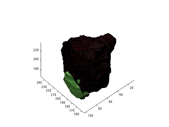
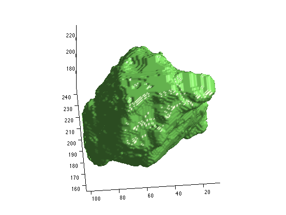
Second, While the maltab format does save out the geometric information, it is encoded in the scirunnrrd.axis field. the code snippet you provided ignored the geometric information, which is why it was shifted. You can either add that into your matlab code, or move the layers to the same group before exporting. You can use the resample tool to move them to the same group with ‘Resample to Match Another Group’ option, or shift+left click+drag the layer to the new group. Attached are some images that show the result of the resampling.
Third, when you export layers together in the export segmentation tool that are not part of the same group (have the same geometry), the exporter does it wrong (naively). It gives a result similar to matlab, ie, without the spacial information, and it is worse if the size of the volumes are different. I would suggest moving all the relevant layers to the same space. You may need to use the padding script I sent you to create a space that will fit all of your layers so that none of them are cut off. then use the resampling too or the shift click and drag to move them to the new space.
cheers,
Jess
On Feb 9, 2016, at 4:14 AM, Sander Land <sander.land@gmail.com> wrote:SanderHi Jess,
Importing the nrrd also has the hole 'punched out' by the other component, so I think this is likely happening in the exporter rather than in the reader.Thanks for the script, I'll use it in any future cases with this problem. I think for the current one I will try to export the translated component separately and stitch them together in Matlab, as I don't want to re-do the segmentation.Best wishes,_______________________________________________On Mon, Feb 8, 2016 at 6:10 PM, Jess Tate <jess@sci.utah.edu> wrote:Hi Sander,The 2D viewer will be bound by the label that is highlighted (blue), so that if you have the original volume highlighted, you won't be able to see slices of the extended volume. By changing selected layers as needed, you should be able to see every slice of every volume.exporting and importing into matlab can be a bet tricky, as it will depend on your reader in matlab for the nrrd format. Make sure that it accounts for the spacing and origin and then make sure that the functions you are using do the same. What happens when you try to reload it into Seg3D?There are a few tools in Seg3D for resizing a volume, such as the resampling tool, transform tool, and the crop tool. extending the grid, ie, padding a volume, is not yet a tool in Seg3D, but can be done using the python console. I will attach a python function that you can use. To use this code, open the python console in Seg3D (from the Window menu) and type the foloowing (you cannot paste multiple lines):exec(open('[path_to_the_script]/padding.py').read())path='[path_to_your_data]'padding(path+'Segmentation.nrrd',path+'test_pad',[10,10,10])The padding script takes the filename of the volume to pad (must be a nrrd), the filename without extension to save the output, and the padding parameters for each direction. The example above will pad the volume by 10 voxels, adding 20 voxels in each direction.cheers,JessOn Feb 8, 2016, at 4:56 AM, Sander Land <sander.land@gmail.com> wrote:Hi Jess,Somebody else created the project, and I'm not even sure how they got bits to be outside the image volume. Going back to the original project it looks like "mask layer -> transform". The "X" slice view does not go down further than the original volume either. Exporting to .nrrd and reading that in matlab has the same result as exporting to matlab.
I think the exporter is confused about the two layers not being aligned, but I'd sort of expect the export function to export what I see on the screen regardless.
Anyway, starting over I don't see any options for extending or resizing a grid, where can I find this?Thanks,SanderOn Fri, Feb 5, 2016 at 7:18 PM, Jess Tate <jess@sci.utah.edu> wrote:Hi Sander,There may be a couple of things going on here. The simplest thing to check is to make sure that you are exporting and importing the right layers. to create the segmentation 'out of bounds' you needed to expand the grid, which it seems that you did. Then you need to copy the entire layer to the new grid and save out the segementations from those new layers. You can try right clicking on the desired layer to export it also.The matlab format from Seg3D doesn't save the spacial information, if I remember correctly. That means if you have two volumes of different numbers of elements, one may be shifted depending on where the origin is supposed to be (as matlab will just set it to 0,0,0). It could also be the wrong size depending on what the relative spacing is supposed to be.cheers,JessOn Feb 5, 2016, at 4:09 AM, Sander Land <sander.land@gmail.com> wrote:Image 3: viewing in matlab, with hole clearly visible on the left.Image 2: Exporting, see the cap is component 7.Image 1: `cap' visible outside image range.Here are some screenshots:Hi Jess,I am using File->Export Segmentation. Both 'to matlab' and 'to nrrd' have the same problem.
http://imgur.com/a/Y5knbAs there does seem to be a component 7 in the matlab data, I've tried to see where it ends up, and turns out the problem is even worse than simple omission.
Component 7 gets translated to somewhere else in the volume and intersects with it, as shown here: http://imgur.com/a/tyCwd(output of figure(1); clf; isosurface(scirunnrrd.data == 1,0.5); hold on; p=patch(isosurface(scirunnrrd.data ="=7,0.5));set(p,'FaceColor','r');" axis equal)Thanks,SanderOn Thu, Feb 4, 2016 at 4:57 PM, Jess Tate <jess@sci.utah.edu> wrote:Hi Sander,
It’s a little tricky to understand what is going on, because when you export a segmentation, it should just save out the entire label mask. Is it possible you are exporting the original image on accident? You can try the 'Export Segmentation' option in the file menu, which has more controls than right clicking on the layer and exporting it that way. If that isn’t working, a screen shot may help determine what is going on.
cheers,
Jess
> On Feb 4, 2016, at 5:05 AM, sander.land@gmail.com wrote:
>
> I have an image data set which is missing a small part due to the bounds of
> the imaging. I've filled this in using the paint tool to make a smooth shape.
> However, when exporting the data set it's cut off again at the original
> bounds. Is there a way to extend these bounds and export the entire
> segmentation?
>
> Thanks,
> Sander
Seg3d mailing list: Seg3d@sci.utah.edu
http://www.sci.utah.edu/software/seg3d.html
To unsubscribe, email sympa@lists.sci.utah.edu with the "unsubscribe seg3d" in the message body.
- [Seg3D] Exporting segmentation out of original bounds, sander.land, 02/04/2016
- Re: [Seg3D] Exporting segmentation out of original bounds, Jess Tate, 02/04/2016
- Re: [Seg3D] Exporting segmentation out of original bounds, Sander Land, 02/05/2016
- Re: [Seg3D] Exporting segmentation out of original bounds, Jess Tate, 02/05/2016
- Re: [Seg3D] Exporting segmentation out of original bounds, Sander Land, 02/08/2016
- Re: [Seg3D] Exporting segmentation out of original bounds, Jess Tate, 02/08/2016
- Re: [Seg3D] Exporting segmentation out of original bounds, Sander Land, 02/09/2016
- Re: [Seg3D] Exporting segmentation out of original bounds, Jess Tate, 02/09/2016
- Re: [Seg3D] Exporting segmentation out of original bounds, Sander Land, 02/09/2016
- Re: [Seg3D] Exporting segmentation out of original bounds, Jess Tate, 02/08/2016
- Re: [Seg3D] Exporting segmentation out of original bounds, Sander Land, 02/08/2016
- Re: [Seg3D] Exporting segmentation out of original bounds, Jess Tate, 02/05/2016
- Re: [Seg3D] Exporting segmentation out of original bounds, Sander Land, 02/05/2016
- Re: [Seg3D] Exporting segmentation out of original bounds, Jess Tate, 02/04/2016
Archive powered by MHonArc 2.6.18.